Hardware workbench
Arduino and ESP-IDF projects show Hardware beside the editor. Target capabilities differ; see Supported boards.
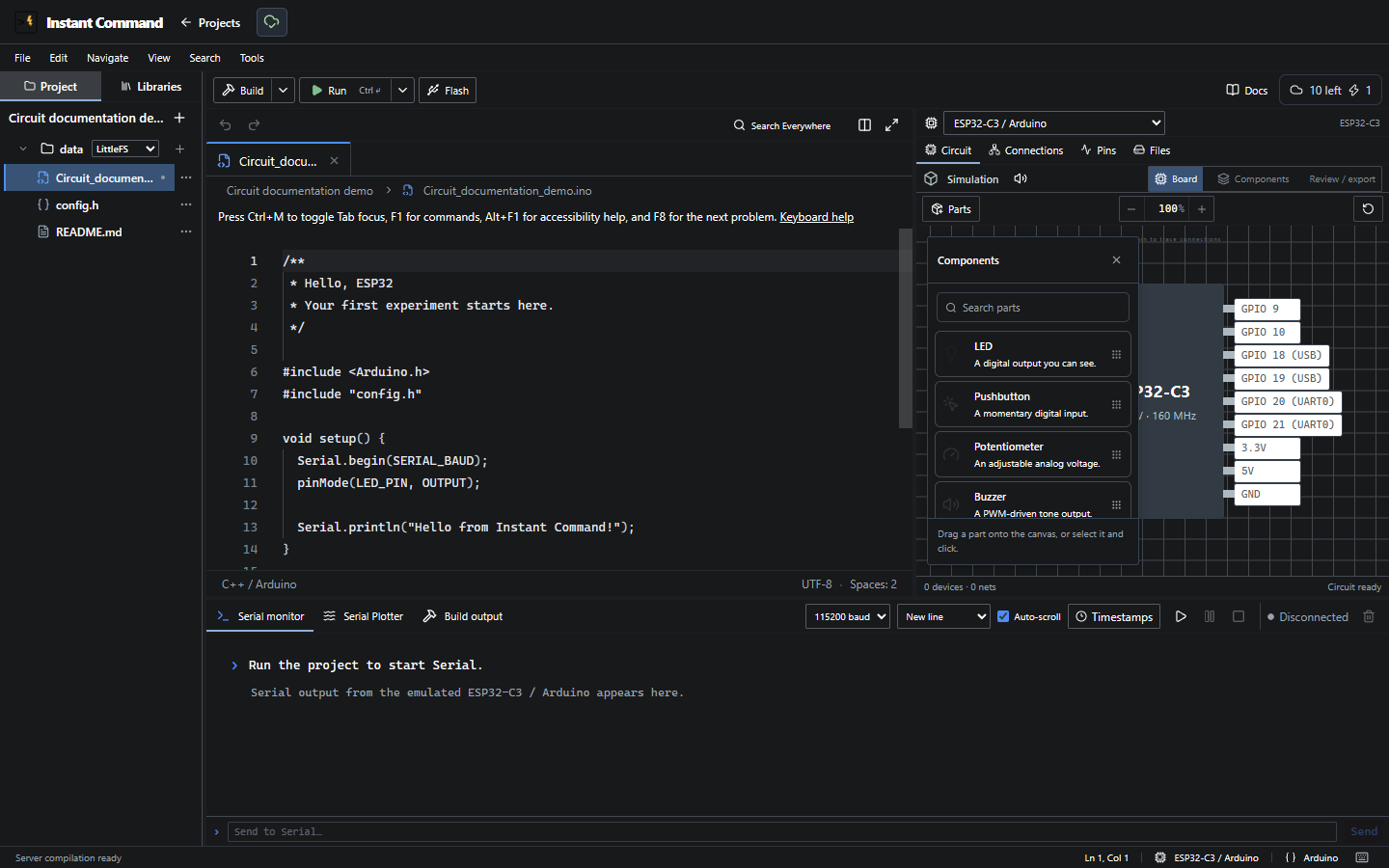
The IDE controls reference explains the visible header, menus, editor and resize controls. The tables below describe Hardware and output.
Hardware and circuit views
Section titled “Hardware and circuit views”| Control | Action / result |
|---|---|
| Project board | Changes target within this framework. Keeps files/libraries; drops connections to pins absent on the new board. Disabled for read-only or busy transitions. |
| Circuit | Opens the simulation workspace. |
| Connections | Lists devices, pins and their current connections; unconnected components are identified. |
| Pins | Lists board pin capabilities; Filter board pins narrows the list. |
| Files | Shows data/ assets; opens loaded text or downloads supported assets. |
| Partitions | ESP-IDF only; loads partition sources before opening the partition editor. Loading errors are reported. |
| Board | Circuit canvas with board and component placement. |
| Components | List-based component properties, connections and supported inputs. |
| Review / export | Circuit review/export view including available signal history. |
| Mute / Unmute simulator audio | Controls browser buzzer sound without changing simulated state. |
| Parts | Opens the searchable component picker. Click-to-place or drag a part. |
| Zoom controls / percentage | Changes canvas scale; background dragging pans the view. |
| Component or pin selection | Opens connection/property tools or traces labeled connections. |
The component catalog includes LED, button, potentiometer, RGB LED, piezo buzzer, LDR, TMP36-style sensor, servo, 16×2 LCD, HC-SR04, motor and H-bridge. Availability of a placed part does not establish complete firmware support.
Buttons, potentiometers, light level, temperature and ultrasonic distance/no-return expose modeled input controls. Power, ground, pin capability and board voltage still matter. A direct 5V ultrasonic ECHO to a 3.3V GPIO needs level handling on physical hardware.
Build, Run, and debugging
Section titled “Build, Run, and debugging”Build compiles; Run starts the supported target emulator after compilation/cache retrieval. Run options → Debug is enabled only for supported browser-debug targets. Pause/resume, stop and restart appear according to runtime state.
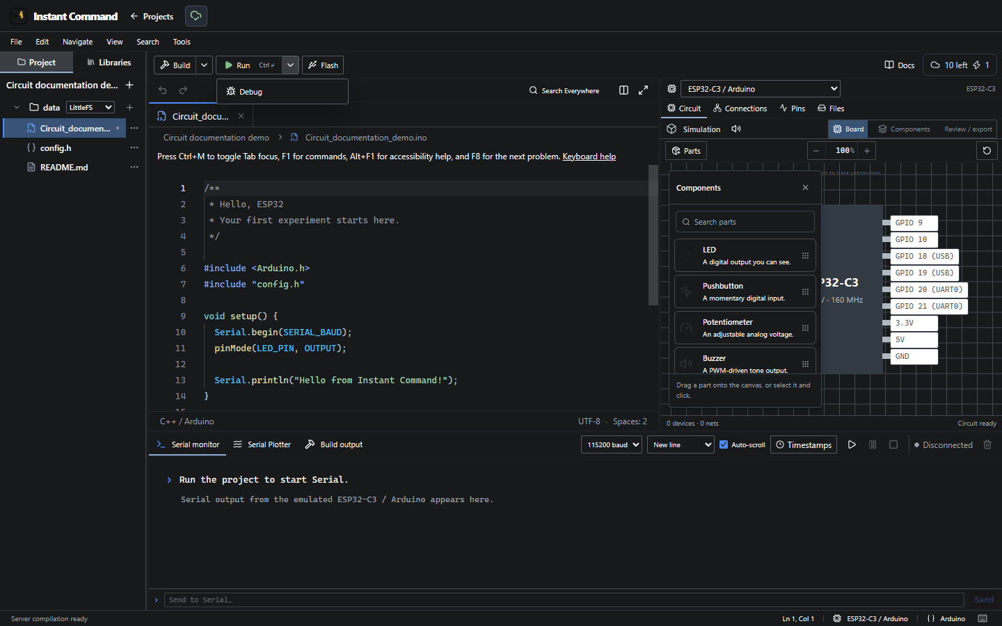
Debugging is supported for Arduino C3 and UNO. ESP32/S3 and ESP-IDF do not inherit that support. A successful build is separate from successful runtime/peripheral behavior.
Serial and output
Section titled “Serial and output”| Control | Action / condition |
|---|---|
| Serial monitor | Shows bounded UART output from this emulator. |
| Baud rate | Select the firmware’s serial rate; defaults resolve to 9600 on UNO and 115200 elsewhere unless saved. |
| Line ending | Chooses the suffix sent with input. |
| Auto-scroll | Follows new output. |
| Timestamps | Adds timing information to displayed serial output. |
| Serial input / Send | Sends text while the runtime accepts input. |
| Clear output | Clears the displayed buffer for the selected output view. |
| Serial Plotter | Plots numeric serial samples. Invalid/non-numeric lines do not become invented readings. |
| Inspect serial samples | Inspects recorded plotted sample values. |
| Build output | Shows compile messages and diagnostics with source links where available. |
| Debugger | Shows supported active debugger information/controls. |
| Project terminal | Opens framework-specific project commands; it is separate from UART input. |
Serial preferences are saved in the project. Changing one option preserves other saved choices. Muting audio or clearing output does not reset the program.
First circuit and troubleshooting
Section titled “First circuit and troubleshooting”Start with an Arduino C3 blink sketch, add an LED, and connect its anode to the sketch’s output GPIO and cathode to ground in the simulation. Physical wiring also needs a current-limiting resistor. Run the sketch and compare serial output with the LED state.
If nothing responds, verify target, build result, power/ground, connections and capability messages before changing code. Check virtual versus physical pin names; the drawing is not physical header order. Browser time is not a real-time electrical guarantee.
The narrow viewport capture is retained in the audit evidence. It does not establish complete mobile or keyboard-only circuit usability.